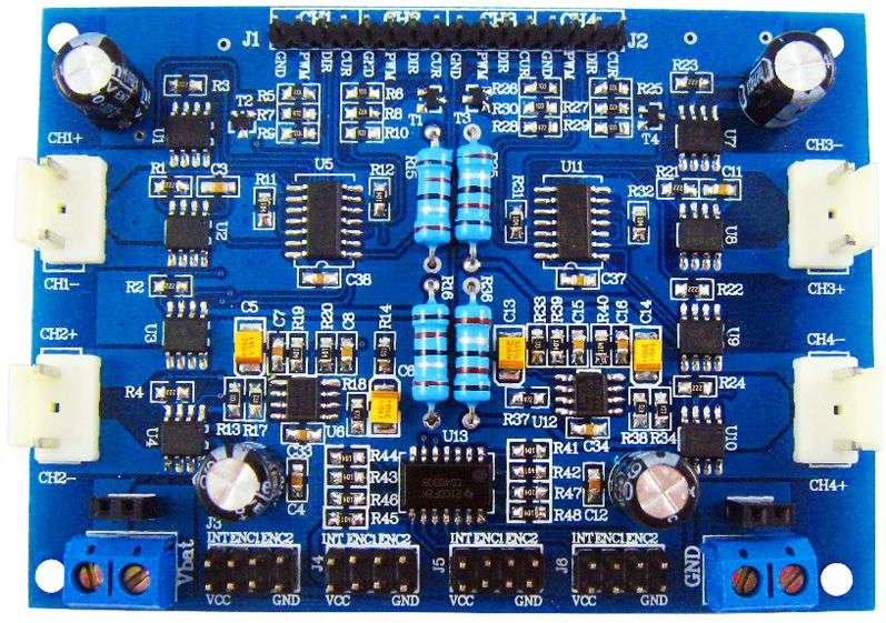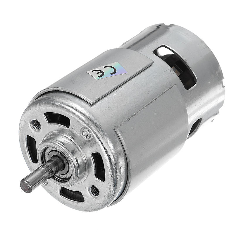

In a sensor-controlled BLDC motor, the control loop is closed via feedback from Hall effect sensors monitoring the motor’s rotating shaft (Figure 1).

High-frequency operation also reduces the uneven electromotive force (EMF) that can result from a less-than-perfect sinusoidal input to the motor coils-decreasing motor vibration and wear. For example, current ripple-an artifact of the alternating current (AC) input after rectification-is reduced, which in turn reduces the size and cost of the passive components needed for filtering. High-frequency operation offers some inherent advantages. Pulse-width modulation (PWM) is superimposed on the base operating frequency to control start-up current, torque, and power. The rotor speed is proportional to the motor’s operating frequency. BLDC motor driver basicsĪ common type of electric motor is the three-phase DC type in which rotor movement is induced by the rotating magnetic field generated by energizing the windings in a controlled sequence (commutation).
#BLDC MOTOR DRIVER CONTROLLER HOW TO#
Along the way, the article introduces sample drivers from ROHM Semiconductor, Texas Instruments, and ON Semiconductor, and discusses how to effectively incorporate them into a motor design. It then explains what to look for in an industrial grade device in order to maximize protection and efficiency while minimizing cost and complexity. This article will briefly cover more driver basics, describing the role of high-current IGBT drivers in modern industrial electric motor applications. Their smaller footprint further increases a high-frequency motor’s power density and saves space. Along with features to boost efficiency, these devices require fewer peripheral devices and have lower operating temperatures.

To address these issues, a new generation of integrated high-frequency gate drivers for BLDC motor applications combines the buffer and boost circuitry needed to drive IGBTs, while also incorporating protection circuitry. Adding this circuitry also complicates and slows down the design process, consumes space, and adds to the bill of materials (BOM). They also aren’t able to level shift the digital controller’s low-voltage output to the higher voltages and currents needed to properly drive IGBTs. However, to operate efficiently and safely, designers need to include buffer circuitry between the BLDC motor controller’s output and the IGBT power transistors.ĭiscrete circuitry comprising bipolar junction transistor (BJT) “totem-pole” circuits can perform this buffering role, but such solutions typically lack protection against high-voltage and high-current transients.

These increasingly rely upon faster insulated-gate bipolar transistors (IGBTs) instead of metal-oxide-semiconductor field-effect transistors (MOSFETs) for faster switching in order to boost power density. In no way does claim ownership or responsibility for such items, and you should seek legal consent for any use of such materials from its owner.In an ongoing effort to reduce costs and lower energy consumption in industrial control applications, designers are turning to high-frequency, high-current brushless direct current (BLDC) motors. Wiring Diagram For Electric Clothes Dryer |Īny content, trademark/s, or other material that might be found on the website that is not property remains the copyright of its respective owner/s. Motorcycle Battery Charger Circuit Diagram | 24v Bldc Motor Controller Circuit Diagram,


 0 kommentar(er)
